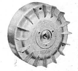
Series 90 Flywheel with Fins
3. Check contact breaker points for correct gap setting
   and see that the breaker arm is free to move.  See that
   the breaker points are clean.  If burnt and badly
   pitted this will indicate a faulty condenser (renew), or
   magneto run with dirt between the points.  (Renew
   " points " if they are in this condition.)
   Check breaker point adjustment screws for tightness.
4. Make sure the nut securing the flywheel is tight and
   that there is no free play of the flywheel.
5. By removing the flywheel examine the internal leads
   for breaks and see they are all properly secured.
   Make sure covered leads are not chafed and earthing.
6. If the insulation of the H.T. coil has broken down it
   will show signs of charring on the outside but it is
   unlikely that this will happen in normal use.
 (Note:  The ignition coil can only be tested with a high
voltage A.C. voltmeter.)
H.T. coil
Removal.  First remove the laminated core complete, then
take off the coil. The core is held to the stator plate on three
studs.  If a lighting coil is fitted as well, see that the thin wire
from it is not wrenched when removing the core.  The H.T.
coil will slide off the core pole after straightening up the brass
tab seen at the top.  Sometimes a fibre wedge may be found
between the coil and core but this is only used to ensure a tight
fit and may not be necessary if another coil is refitted.  Due
to their individual manufacture, coil sizes vary slightly.
Replacement. The small brass tab protruding from the side
of the coil must face towards the flywheel being at the corner
nearest to the felt, cam lubricating pad.  The two leads should
come Out from under the coil when it is on with the short lead
nearest the stator plate.  This short lead is attached to the
core stud for earthing.  The long lead is attached to the -
breaker arm spring block together with the condenser lead.
Bend the leads so that they do not foul the flywheel or cam.
It is most important to refit the red plastic band round the
coil and H.T. lead attachment and to see that it is in good
condition.

Lighting coil
Removal.  This is the smaller coil and can be removed without
dismantling the core.  First, remove the terminal from the
stator plate.  Straighten the brass tab of the core and slide
the coil off.
Replacement.  Replace in the same manner.  Bend the brass
tab back over the coil after fitting to secure tight fit.

Condenser
   A weak or faulty condenser can be detected by badly
burnt and pitted contacts or a continuous, intense blue spark
across the contacts when running.  A very small white spark
across the points when running is normal.
Removal; - Release the condenser lead from the breaker arm
spring nylon block.  Take out the clamp screw seen near the
top of the condenser and ease the condenser out  The bottom
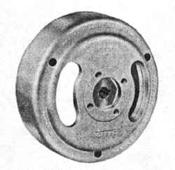
Series 90 Plain Flywheel
The Slots allow easy adjustment of "Points"
clamp is attached to the stator plate only.  Replace in the
same manner.

Flywheel
   This unit is robustly constructed and it is unlikely that
any faults will ever develop.  They are scientifically balanced
before leaving the factory and made of a rust-proof metal.
Attachment of the flywheel to the crankshaft is by taper shaft
and key, locked with nut and shakeproof washer.  The magnets
cast into the rim of the wheel are made of a special alloy and
will not de-magnetize in normal use.  A keeper ring is not
necessary when dismantling.
Removal.  Extractor tools are made and supplied by WIPAC
and should be used when removing the flywheel to save damage
to engine parts.
    First, remove the flywheel nut and lock washer.  Screw
back the main bolt of the extractor to its fullest travel, then
screw the smaller bolts into the flywheel.  Continue tightening
the main bolt until the flywheel is freed.  It is important to
use the small bolts supplied as they are designed to fit without
causing internal damage.
    When replacing the flywheel make sure metalized dust
or small steel items have not been attracted onto the magnets.
Clean the flywheel inside and outside.
    The finned-type flywheel must be removed to check the
contact breaker points as there are no slots.
The contact setting is cast on each type of SERIES
"NINETY" flywheel.

Flywheel extractors
    Two types are available as there are two classes of flywheel.
One wheel has three holes drilled and tapped for an extractor
and the other has four holes. The THREE-hole extractor is
Part No.00586, price 5s. Od. The FOUR-hole extractor is
Part No.00494, price 5s. Od:

Contact breaker points
Gap adjustment. Turn the engine over until the breaker points
are fully open.
    Test with feeler gauge between " points ". The correct
setting is cast on the flywheel but most " NINETY" magnetos
should be 0.0l8".
    If the " points" require adjustment two screw heads will
be seen beside them.  Slacken the large screw and carefully
turn the small screw, which is eccentric, until the correct gap
is obtained.  Tighten large screw.
Removal. The complete contact set may be removed by
taking out the large-headed screw mentioned above and
undoing the two leads in the nylon block.

   It is essential for the best performance to use only WIPAC
spare parts and where possible the name WIPAC is stamped
or cast on the parts. All "SERIES NINETY" magnetos
are guaranteed for six months from date of purchase and should
any fault develop within this time, return it complete to a WIPAC
agent or send it direct to the WIPAC GROUP.