TWO-STROKE engines with flat- topped pistons, of which the latest Villiers Junior de luxe engine is an example, differ from the more familiar deflector piston type chiefly in the design of the ports and in the characteristics of their performance. The operating principles are, broadly speaking, the same. For the benefit of those whose experience has hitherto been confined to purely pedal-propelled bicycles an explanation of the functioning of the two-stroke engine is included. HOW THE TWO-STROKE WORKS A flat-topped piston in a cylinder is connected to a crank. As the crank is turned through one revolution the piston travels once down and once up. Every down stroke is a firing stroke, i,e., there is an explosion of gases every two strokes of the piston as distinct from once in every four on a four-stroke. In other words, there is one explosion in the cylinder for every revolution of the crank. If a study is made of the diagrams which illustrate the cycle of operations it will be |
|
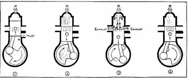
What happens inside a two-stroke engine with flat-topped piston. 1. On the
upstroke of the piston a vacuum is created in the crankcase, the piston un-
covers the inlet port and the mixture enters. 2. The piston descends, com-
pressing the mixture. The previous charge is fired, which causes the descent
of the piston. 3. At the bottom the piston uncovers the exhaust and transfer
ports burned gases rush out and fresh mixture enters. 4. The piston starts a
new cycle by compressing the fresh mixture
gas from the carburettor is drawn into the crankcase through the inlet port, is trans- ferred to the combustion space by the transfer ports, and is expelled as burnt gases via the exhaust ports. The cycle of operations is as follows :Ś (1) The piston rises, uncovering the inlet port, and gas is sucked into the crankcase. Simultaneously the crown of piston compresses the previous charge in cylinder head. (2) When the piston nears the top of the stroke this compressed charge is fired, the piston travels down, compressing the gas in the crankcase and delivering power to the crankshaft through which it is transmitted to the rear wheel. (3) The piston uncovers the exhaust ports, spent gas still at fairly high pressure rushes out into the silencers. Fractionally later the four transfer ports are uncovered, and the new charge from the crankcase is released into the cylinder. The design of the transfer ports, which enter the cylinder tangentially and inclined upwards, helps the new charge to clear the burned gas without mixing with it. (4) The piston rises, closing all ports, and a fresh cycle is begun. OVERHAULING THE ENGINE DECARBONISING When an engine has run for a consider- able mileage deposits of carbon are formed in the combustion space of the cylinder head, in the piston crown, under the piston rings and round the edges of the ports of the cylinder. This deposit affects the efficiency of the engine and must be removed. The engine need not be removed from the frame, but the following parts must be removed from the engine :Ś (1) Cylinder head. Using a screwdriver, remove the release valve control clip. (On some machines side shields are fitted ; these must be removed.) Remove the four nuts securing the head in position after having taken out the sparking plug and the release valve complete. The piston crown and cylinder head can now be cleaned, but as it is more than likely that the ports, ring grooves and silencing system also require decarbonising it will be necessary to remove the cylinder. (2) Remove the carburettor, exhaust manifolds and, where fitted, the long tail |
pipe. The silencer can then be removed. Remove the four nuts securing the cylinder to the crankcase. The cylinder can now be pulled away, but do not turn it while doing this, as the piston ring joints may foul the ports. If the cylinder base joint washer is damaged, replace with a new one on reassembling the engine. (3) To clean the piston skirt and ring grooves it is advisable to remove the piston. Remove the circlip from one end of the gudgeon pin hole. The gudgeon pin is a floating fit, and will push out unless carbon deposit prevents this, when an extractor of the band type is useful. Remove the rings from the piston with great care as they are very brittle. Clean out the grooves and the carbon from the rings. A section of an old piston ring ground to a point makes an admirable tool. A knife will do, however. The piston, being of aluminium, is soft, so care should be taken not to remove any metal. Scrape the piston crown and the inside of the piston clean with a stick of solder cut or hammered to a chisel shape. The piston crown may be lightly polished. Wipe off all traces of polish and do not let it touch the piston skirt. (4) Clean out the various ports of the cylinder with a screwdriver or old knife. A bent tool will clean round corners more easily. The by-pass hole from the exhaust port to the top face of the cylinder must be cleared of carbon. Be careful not to damage the walls of the bore or the top face of the cylinder, which has to make a gaslight joint with the cylinder head. FITTING NEW RINGS When fitting new rings, test them in the cylinder by pressing them just inside the bore with the skirt of the piston. The gap between the ends should be 0.004in. to 0.008in. Too small a gap will cause a seizure. An old ring with gap more than 0.030in. needs replacing. Note the way the rings were originally fitted and replace exactly the same, dead square in the groove. REMOVING UNIT FROM FRAME The Villiers Junior de luxe is fitted to many of the leading motorised bicycles and the method of engine removal is apparent. |
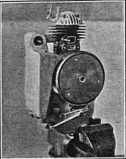
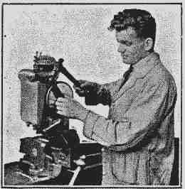
How to mount the engine for attention to the cylinder and flywheel. One of the two exhaust manifolds has been removed Disconnect the rear chain and all controls and connections, including petrol pipes, throttle, choke and release valve control wires and lighting connection, take off the carburetter and the exhaust pipe stays if fitted. Engine and engine plates will usually come away together after removal of the securing bolts. NOTE.ŚA con- nection is provided in the lighting cable, a short distance from the magneto ; un screw this when removing engine from frame. Do not attempt to remove cable from inside magneto ; keep in position the rubber sleeve over the connection, otherwise a short circuit may occur. STRIPPING DOWN Stand the engine upright by holding the bottom lug in a vice. Remove exhaust and inlet manifolds, and the nut holding the silencer to the clutch case. Remove the two slotted screws in the clutch cover in order to lift off the clutch bridge piece and lever complete, thus revealing the driving sprocket. When the engine is taken out of the vice it is advisable to tip out the clutch operating push-rod, which consists of three sections and a ball. The outer section will probably come away with the bridge piece. |
MAGNETO To remove the magneto flywheel undo the nut, using a 7/16in. spanner and hammer. A special " hammertight" spanner is marketed by Villiers. NOTE.ŚThis nut, right-hand thread, has a flange which draws the flywheel off as it is unscrewed. After the first turn or two it will be found to tighten because the flange is pulling against face of the jiywheel boss. Place a piece of wood against the face of the nut and give a sharp hammer blow. The flywheel will then be loosened on its taper and the nut can be turned with the fingers. Having removed the flywheel place a spanner or piece of iron across the pole shoes to prevent loss of magnetic flux. Releasing four screws in the centre now enables the armature plate, magneto com- ponents and contact breaker to be taken off as a unit. If these screws are obdurate, tap the end of the screwdriver sharply with a hammer before turning. The contact breaker points are accessible without removing the flywheel, by remov- ing the three small screws which secure the large disc in front of flywheel. REMOVING CYLINDER This operation has already been detailed under " decarbonising." |
CLUTCH Lay the engine on its side with the pro- truding shafts uppermost and remove the seven nuts and washers holding clutch cover. Remove the sprocket from the clutch shaft by unscrewing hexagon nut (right-hand thread) anti-clockwise. On later models there is a lock washer under- neath the nut which must first of all be flattened to allow the nut to turn. Pull off the sprocket, using a claw type ex- tractor, and remove the key from the shaft. The clutch cover can now be removed by tapping gently the ears provided on the cover, both ends at the same time. With the cover off the primary chain, engine sprocket and clutch sprockets are revealed. On the other side of the case is a small nameplate held in position by four slotted screws. When this cover is removed the clutch shaft can be drifted through from that side, bringing away the complete clutch, which will drop apart when released from the chain. If the chain is very tight it may be necessary to remove the mainshaft sprocket, but after some service the chain is usually slack enough to dispense with this, as it will ride off when the clutch sprocket is tilted. To remove the mainshaft sprocket first flatten the lock washer fitted under the nut, wedge the connecting rod in the crankcase to prevent turning and undo the nut with an 11/16in. box spanner. The sprocket will now come off leaving the key in position. CLUTCH REASSEMBLY The clutch must be assembled as a unit before replacing it in the chain case. Hold the shaft with the threaded end upwards and slide on the short spring sleeve (1), spring (2), long sleeve (3) and outer clutch plate (thick plate with six holes) (4), shiny side uppermost. Press down the plate and insert the flat cotter (5) in the slot in the shaft, with the ears towards the top. Then assemble the cork insert plate (6) with the driving tangs upwards, the centre plate (dished) (7) with the bulge downwards, followed by the driving sprocket (8), either way on, the solid outer plate (9) and the ball race. In order to engage the outer plate with the splines on the shaft the whole assembly must be compressed and held until the |
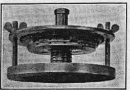
Special jig for compressing the clutch spring. If this is not available the procedure outlined in the text is quite effective clutch case cover has been secured in place. A special jig is used at the factory, and the Villiers Company can supply a simple jig, but in the absence of this aid the simplest way is to proceed as follows :Ś Obtain a tubular distance piece 11/16in. long and not more than 3/4in. in diameter which will fit easily on the shaft, and assemble this over the ball race. Then take a piece of steel rod 3/16in. in diameter and about 3in. long. Insert this in the hole down the middle of the shaft and thread the nut over it. Lift the whole assembly carefully and place it endways between the jaws of a vice. Tighten the vice so that the push-rod compresses the clutch spring. This will enable the nut to be screwed on to the end of the shaft and tightened gently. Fit the chain round the clutch sprocket and replace the assembly in the chain case, passing the chain round the engine sprocket before pushing the clutch home in the ball race at the back. Replace the name plate. The cover can now be fitted, and it will be found that the nut on the end of the clutch shaft protrudes through the hole. If the cover is heated slightly in boiling water before fitting it will drop over the ball race quite easily. Do not omit the thin jointing washer. When the nuts holding the cover have been tightened down the nut can be removed from the shaft and the distance piece replaced by the sprocket, after the Woodruffe key has been inserted. Tighten the nut fully and turn up the lock washer (if fitted). Then with the unit lying on the bench insert the sections of the clutch operating push rod, long section first, then ball, short |
section and medium section, the last fitting in a bush in the bridge piece, which should be attached last. When the unit is replaced in the frame check the adjustment of the clutch control wire, and adjust with the grub screw and lock nut on the lever .on the bridge-piece so that there is slight play on the lever, ensuring that the clutch is fully engaged and that the push-rod is not in compression under normal running Conditions. BIG END AND CRANK CASE When the clutch is down the only material part left to strip is the crank assembly. Remove the right-hand crank- case cover and take out the key in the protruding end of the shaft. Using a soft hammer, tap out the shaft, connecting rod and crank assembly complete. RENEWAL OF BEARINGS All bearings can be renewed, but a certain amount of skill and care is needed, and renewals should not be undertaken unless they are thoroughly understood. The little end of the connecting rod has a bronze bush which floats in the rod and on the gudgeon pin. Three 3/16in. oil holes are drilled round the bush. The gudgeon pin hole in the piston is bushed, the bushes having grooves for the locating circlips. Renewal of the big end bearing calls for a press. First drive out the rivet through the crankpin. This releases the large washer which retains the rod and rollers on the pin. There are eight steel and eight bronze rollers. The pin can be pressed out from the back. New pins are supplied 0.001in. oversize on the part which is pressed into the crank web. An oversize pin must always be used as once a pin has been pressed in and extracted, the hole is slightly enlarged. Press in the new pin, using a pilot to ensure that it goes in absolutely square. Assemble the rod and rollers (putting the bronze rollers between the steel ones) with a generous smear of engine oil, and rivet the washer on, punching the end of the rivet into the slots in the washer. Should the main ball bearing require renewal remove the retaining plate screwed to the inside of the crankcase and tap out the bearing from the other side. Note the |
crankcase sealing gland which is retained by the ball race and consists of a flat steel spring washer, slightly dished and slotted, and a bronze bush. It should be noted that the bush is a very close running fit on the crank shaft, being internally ground, but is a loose fit, with about 0.030in. clearance, in the crankcase. The seal is actually made by the flange of the bush being pressed against the face of the crank- case by the spring washer. When assembling a new bearing insert the bush and place the spring washer over it with the dish towards the bush. Press in the bearing and replace the retaining plate. The hole in the chaincase cover through which the crankshaft passes is sealed with a bronze bush pressed into the cover out- side the ball-bearing. As the load is taken by the ball-bearing this bush should never need renewing. When reassembling the engine note the paper washer which goes between the two halves of the crankcase and the 1/32in thick jointing washer between the base of the cylinder and the crankcase. There is no gasket of any kind between the cylinder and head. Jointing compound should not be used on any of these joints. Tighten all flange nuts a little at a time, going from side to side or, in the case of the cylinder base and head, from corner to corner, tightening " opposite " nuts in sequence. If the cylinder becomes worn or badly scored it can be rebored, but a very high finish is desirable. Replacement pistons are available in 0.015in. and 0.030in. over- sizes. When reboring measure the piston skirt accurately and allow 0.004in.-0.005in. for skirt clearance on the diameter. CARBURETTOR Reference has been made to the gas filling the crankcase by way of the inlet port, and it may be as well to explain how this gas is formed, for the benefit of those unacquainted with petrol engines. The carburettor is responsible for this function and on motor-assisted bicycles this Villiers instrument contains three main partsŚthe float chamber, the throttle and the mixture control needle. Petrol enters the float chamber from the petrol tank by way of an orifice (E) which can be sealed by a tapered needle |
valve (F). The air-filled brass float rises when the petrol flows in and when it reaches a certain height forces the needle valve on to its seat and stops any further flow of fuel until the engine's demand for fuel has again lowered the level. Petrol passes from the float chamber through a jet in which slides a long needle with a fine taper (D). This needle is connected |
with the throttle (C), which is cylindrical in shape and slides up and down across the passage through which air passes to the engine. When the engine is not required to produce much power the throttle is nearly in its lowest position and the mixture control needle fills the jet orifice. Thus only a small amount of air is allowed to |
pass and an equally small amount of petrol is sucked from the jet to mix with the fast moving air-stream and thus be vaporised. When the rider needs more power he opens his throttle lever which raises the throttle plunger and allows more air to pass to the engine. At the same time the throttle plunger lifts the mixture control needle and allows more petrol to emerge from the jet. Thus the proportion of petrol to air is kept constant at all positions of the throttle. TRACING TROUBLE Troubles are usually traceable to dirt on the float chamber needle, causing creep or flooding, or dirt in the filter, loose top cap, punctured float, air leak through fixings becoming slack, air-lock in tank (cure by removing petrol cap and blowing into the tank), too much or wrong kind of oil in petroil mixture, choked fuel pipe or tap. The strangler, of course, is only used to give rich mixture on starting. Release when the engine is warm or starts to " four-stroke " when running or idling. DISMANTLING It is best to detach the carburettor from |
the engine. Unscrew the top ring A and lift out the throttle slide C. Invert the instrument and unscrew the bottom nut B. Take off the fibre washer, lift off the cup C and float H, undo the small grub screw in the side of the body. Push out the centre-piece and jet J, noting the position of the fibre washer under the head. The lever controlling the fuel needle can now be pushed aside and the needle removed. A screw-on type of air filter is fitted, the gauze of which should be cleaned at intervals by dipping in petrol. ADJUSTMENT To adjust the needle first of all remove the throttle by unscrewing the top ring. At the head of the throttle there is a small slotted screw K. Turning this in a clock- wise direction lowers the needle and will give a weaker setting. Turning in an anti-clockwise direction will give a richer setting. For adjustment give approxi- mately half a turn at a time until it is found to be correct. As a starting point if the adjustment has been entirely lost, the top of the screw should be about two |
threads or 1/16in. below the top of the throttle. If the float cup has to be removed at any time for cleaning, when re-assembling do not use too much force in tightening the bottom nut. Periodically see that the gauze in the petrol pipe " banjo " con- nection L is free from dirt, or the petrol will not flow freely. IGNITION To fire the charge of petrol gas when it is compressed in the cylinder an electric spark is required. This is produced by a magneto, an instrument which produces electricity at a very high voltage. To produce that voltage a rotating magnet builds up a current in a coil of wire. At the instant when the spark is required that current is prevented from flowing by the separation of two contacts operated by a cam on the crankshaft. A sudden surge of current is caused in the primary coil, and by a process known as induction this surge causes another current of a very much greater voltage to flow in a secondary coil which surrounds the first or " primary " coil. From the secondary coil an insulated cable takes the momentary high voltage to the sparking plug, which is screwed into the top of the cylinder head and consists of a central rod to which the high-tension cable is connected. This central rod or electrode is insulated from the main body of the plug, at the innermost end of which is a small projection almost touching the central electrode. Electricity must always flow in a circle, and here the high tension current flows through the secondary coil, along the high-tension cable, down the central electrode, whence it jumps to the body of the plug over the small gap pro- vided and returns to the secondary coil by way of the cylinder and crankcase. When it jumps the small gap it forms a spark and thus ignites the mixture. MAGNETO AND TIMING The contact points in the magneto are enclosed in a circular brass case. (On early models this has a cap attached by a |
|
feeler gauge supplied with the magneto, then re-tighten the locknut. Never file the points. Clean if necessary with a non- woolly rag dipped in petrol. SPARKING PLUG The gap between the side and central electrodes should be 0.020in. In use the points of these electrodes get burnt, thus causing the gap to widen . Close up the gap by bending the side electrode. Never bend the central electrode . If there is plenty of fuel in the carburettor and the engine fails to start, remove the sparking plug and examine the points, which may be bridged by a film of oil. Clean thoroughly in petrol. LUBRICATION Petroil lubricationŚa mixture of 1/2 pint of the recommended grade of oil with each gallon of petrolŚis employed. It is of the greatest importance that this mixture should be made in its correct ratio of one part oil to 16 parts petrol, and it must be well shaken in a tin to ensure thorough mixing before pouring into the tank. Never pour the oil and petrol separately into the tank and trust to vibration for mixing them. |
|
Manufacturers of the Junior-de-Luxe
EngineŚ
The Villiers Engineering Co., Ltd.
Marston Road Wolverhampton
Telephone : Telegrams :
Wolverhampton 21666-7-8 Villiers, Wolverhampton
|
The following is a copy of the Guarantee supplied with every VILLIERS " Junior-
de-Luxe " Engine :Ś
WE GUARANTEE, subject to the conditions mentioned below, that all precautions
which are usual and reasonable have been taken by us to secure excellence of materials
and workmanship. This guarantee is to extend and be in force for 3 months from the
date the Engine or Accessory is despatched by us, and during this period we will replace
free of charge any part manufactured by us which may prove defective in workmanship
or material.
CONDITIONS OF GUARANTEE.ŚIf any part is claimed to be defective, the
part or the Engine must be sent to us carriage paid and accompanied by an intimation
by the sender that he desires to have it repaired free of charge under our guarantee.
At the same time the number of Engine and full particulars of purchase must be furnished.
Failing compliance with the above, no notice will be taken of anything that may arrive,
but such articles will lie here at the risk of the sender, and this guarantee or any implied
guarantee shall not be enforceable.
As VILLIERS Engines and Accessories are liable to derangement by neglect or
misuse, this guarantee does not apply to defects caused by wear and tear, misuse or
neglect. In the case of Engines and Accessories which have been used for " hiring
out" purposes, or from which our Trade Mark, name, manufacturing number or any
instruction plate has been removed, no guarantee of any kind is given or is to be implied.
VILLIERS Engines and Accessories used for purposes other than Motor Cycles
or Motorised Bicycles, are hot included in this or any guarantee, unless the purpose for
which they are used has been approved and agreed by us in writing to come within the
terms of this guarantee.
We do not undertake to bear the cost of the re-fitting or replacement of any part, nor
do we accept responsibility for postage, carriage or any other charges in connection with
the replacement of any part.
The term "Agent " is used in a complimentary sense only, and those firms or
persons whom we style our Agents are not authorised to advertise, incur any debts or
transact any business whatsoever on our account other than the sale of goods which they
may purchase from us, nor are they authorised to give any warranty or make any represen-
tations on our behalf or sell subject to or with any conditions other than those contained
in the above guarantee.
The Villiers Engineering Co., Ltd., cannot accept responsibility nor be held in any
way liable for damage to or loss of complete Motor Cycles, Engines or any parts thereof
through fire or any other cause when in their possession. If complete Motor Cycles are
sent for repair or adjustment, they can only be ridden and-tested on the road at the
owner's risk, and without responsibility on'the part of the Villiers Engineering Co., Ltd.
The Makers of the VILLIERS " Junior-de-Luxe " Engine make a special offer to
overhaul any Engine within 12 months from date of its original purchase at a price not
exceeding 38s. nett. This includes attention to Engine, Flywheel Magneto and Car-
burettor, and the fitting of any new Parts which may be necessary through normal usage.
Full particulars of this scheme are supplied in the Instruction Book furnished with every "
Junior-de-Luxe " Engine.
|
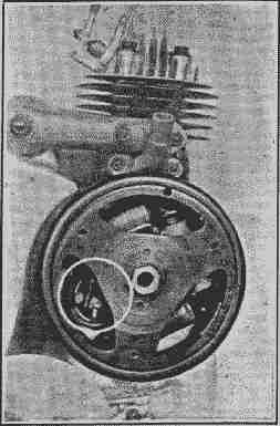 Access to the magneto contact-breaker is
gained by removing the flywheel cover
plate. The breaker unit is visible inside
the white circle
Access to the magneto contact-breaker is
gained by removing the flywheel cover
plate. The breaker unit is visible inside
the white circle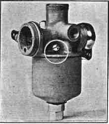 View of the Villiers carburettor, showing,
in the white circle, the grub screw which
must be taken out before the centrepiece
and jet " J " can be removed
The chaincase is lubricated separately
through a filler plug, a different grade of
lubricant to that used for the engine being
recommended (see " Tabulated Data " on
p. 2). It is important that the level of
oil should be maintained.
 View of the Villiers carburettor, showing,
in the white circle, the grub screw which
must be taken out before the centrepiece
and jet " J " can be removed

  The chaincase  is  lubricated  separately
through a filler plug, a  different  grade  of
lubricant to that used for the engine being
recommended (see " Tabulated Data " on
p. 2).  It  is  important  that  the  level  of
oil should be maintained.