VILLIERS ELECTRIC LIGHTING SETS
DIRECT LIGHTING SYSTEM
(without Parking Battery).


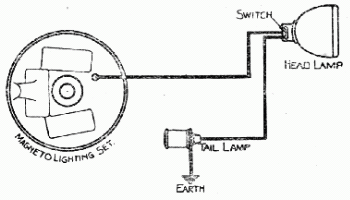
The wiring in this system is exceedingly simple, and so far as the rider is concerned, consists only of one cable taken from the back of the Armature plate in the flywheel magneto to the head lamp and thence to the tail lamp, the two being wired in series. The correct bulbs to use are- 6 volt .5 amp. in the head lamp, and 4 volt .75 amp. in the tail lamp.
   Owing to its simplicity, there is very little likelihood of the rider being stranded on the road with this lighting set. Should the filament of one bulb break, perhaps through vibration, the other bulb will go out owing to the set being wired in series. To get home, a temporary repair can be made by fitting the tail lamp bulb into the head lamp if the bulb in the latter has broken, and then breaking the glass of the damaged bulb, fitting it into the tail lamp and twisting the two ends ot the broken filament together. This will complete the circuit and enable a light at the head lamp to be obtained.
The connection at the magneto end consists of a split terminal at the end of the cable, which is pushed into its socket. This terminal must be kept quite clean to give good contact, and if it shows a tendency to become loose and vibrate from its holder, the two prongs of the terminal should be opened out slightly to give them a greater pressure against the sides of the socket.

ACCUMULATOR CHARGING SET
(Early Pattern without Rectifier).

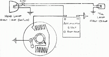
   In this equipment the alternating current generated by the coils is converted through a commutator to D.C. (Direct Current) —(not to be confused with the "Direct Lighting" set, the current in which is actually alternating)—and conveyed to the accumulator, whence it is distributed to the lamps.

In this system the wiring of the head and tail lamps is arranged in parallel (see Diagram). The bulbs employed with this lighting set are 4 volt 4 watt gas filled for the head lamp, and in the tail lamp, 4 volt .5 watt. These should not be varied. Being in parallel an earth return is made at both head and tail lamp, and in this connection the internal wiring of the head lamp differs slightly from that of the lamp employed with the Direct Lighting set, as one wire is "earthed" to the reflector.

General Care of Accumulator Charging Set.

   It is absolutely essential that a good " earth connection should always be maintained between the bulbs (head lamp and tail lamp), the bodies of the lamps, and the frame of the machine. The carbon brush in the magneto cover, which is in contact with the commutator on the fly wheel, should always be kept a good sliding fit in the brush holder. The brush itself should be replaced before it is completely worn out, as sparking from the brush to the commutator may be caused either by a sticking brush, or one that is so short as to be "rocky," and sparking would obviously very soon damage the commutator.

   The arm of the commutator cut-out should oscillate freely on its centre pin, and its contact surface with the commutator should be kept clean, as dirt or oil at this point would cause sparking and loss of output. If sparking occurs at the carbon brush with consequent blackening of the commutator when the commutator itself is clean and the brush free and not too slack, the mica inserts between the copper segments of the commutator should be examined, and if standing proud, should be carefully touched up with the edge of a smooth file until they just stand below the surface of the metal segments.
If at any time, it is necessary to remove the magneto armature plate, or take the battery charging cable from the bush in the back of the armature plate, it is advisable to disconnect the cable from the positive terminal of the accumulator. This precaution will prevent any possibilities of short circuiting and eliminates any danger of damage to the cable should the loose connection come in contact with any part of the metal frame. Should the battery fail for any reason when on the road, a light can always be obtained direct from the coils in the Villiers flywheel magneto, by disconnecting the cables from the positive terminal of the accumulator. In this case care should be taken to ensure that the terminal does not touch the machine.

Head Lamps.


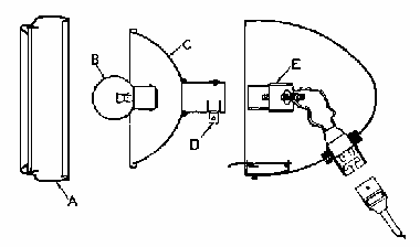
Head Lamp of early pattern Direct Lighting Set and Accumulator Charging Set.


   The front "A" must be pressed in and twisted in an anti-clockwise direction to remove it. The bulb may then be taken out, and if it is required to focus the lamp, draw off the reflector "C," by twisting it until the small pegs are opposite the slots in the body of the lamp, and slacken the thumb screw "D." The bulb holder can then be pushed backwards and forwards in its guide until the correct focus has been obtained, afterwards the bulb holder must be locked in position with the thumb screw.

VILLIERS DYNAMO CHARGING SET.


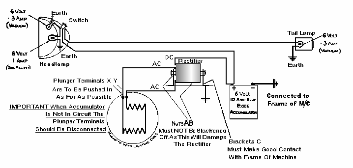
   This Lighting set incorporates a Westinghouse metal Rectifier under licence, and is a full Accumulator Set with none of the delicate parts, such as commutators, cut-outs, and slip-rings, which are necessary with the usual Dynamo equipment. The wiring is quite straight forward, and as there are no moving parts, it is very unlikely for any trouble whatsoever to develop in this equipment. On no account should the rider attempt to dismantle the Rectifier, or to remove it from its case. There is nothing moving inside this case, and everything has been assembled correctly before despatch.       The correct bulbs to employ are as follows: -
      Head Lamp Main Bulb - 6 volt 1 amp. gas-filled;
      Head Lamp Pilot Bulb - 6 volt .3 amp. vacuum;
      Tail Lamp Bulb - 6 volt .3 amp. vacuum, and for efficient results these should not be varied.

The wiring of this set is shown by the diagram

The following remarks are IMPORTANT and should be observed by the rider in the event of any difficulties:-
  1. THE RECTIFIER MUST NEVER BE TAKEN APART. This means that the nuts "A" and "B" (see diagram) must on no occasion be loosened, as this will destroy the necessary contact of the plates and reduce the efficiency of the Rectifier.

  2. It should never be necessary to remove the Rectifier from its case.

  3. Should it be required to remove the Rectifier and case from the machine, the Positive ( + ) Terminal should be disconnected from the Accumulator, and the Plunger Terminals "X" and "Y" should be pulled out from the Armature Plate at the back of the Flywheel Magneto.

  4. On no account must the Engine be run when The Accumulator has been removed and the Rectifier is still in circuit. To prevent damage, pull out the two Plunger Terminals from the Armature plate at the back of the Flywheel Magneto.

  5. The Plunger Terminals " X " and " Y " must be pushed in their sockets as far as possible to make good contact.

  6. The Brackets "C" of the Rectifier must make good contact with the frame of the machine.

  7. Clean off all enamel where earth contacts are made.

  8. The Rectifier must not be fitted near the Cylinder or in any other position where it will be subject to heat.

  9. The Rectifier must be kept dry, as oil or water between the fins will cause a short circuit.


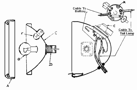
Head Lamp for Villiers Dynamo Charging Set.

   To remove front "A," press in and twist in an anticlockwise direction. The main bulb "B" is screwed into the coils of a spring "D" which holds it in any desired position. By this means a very sensitive adjustment of the focus is obtained, as turning the bulb either to the right or left moves it backward or forward. The pilot bulb "F" is held in position by the usual bayonet clip and the bulbs are connected by spring contact to the switch at the top of the lamp.

The knurled nuts "X" should on no occasion be removed or tightened.

Accumulators.
   With the Villiers Charging Set supplied during 1928 and 1929. the "Nife" Accumulator was used in many cases. This is a nickel-iron accumulator requiring quite different treatment from the ordinary lead type of accumulator. Full particulars regarding the care and handling of the "Nife" Accumulator are obtainable from Batteries, Ltd., Hunt End Works, Crabbs Cross, Redditch.
   The alternative type of accumulator supplied is the "Exide" type, which is also standard on the new Villiers Dynamo Charging Set incorporating a Westinghouse Rectifier under licence. Full particulars of the "Exide" battery are obtainable from The Chloride Electrical Storage Co., Dale End, Birmingham.

PARKING LIGHT SETS,
(with Stand-by Dry Batteries).


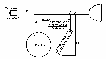
   There are various Parking Light Sets with Dry Batteries to give a stand-by light when the Motorcycle is standing. These are generally classified by the approximate size of Head Lamps, as follows:-
      All Parking Sets are wired in parallel.

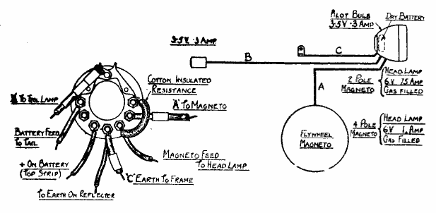
   5-in. SET. The Head Lamp contains one Bulb and a Three-way Switch giving "Off," "Full, and "Dim" positions. A Torch-type Battery is incorporated in the wiring, and the cable at the Magneto end plugs in, in the same manner as the ordinary Direct Lighting equipment. Motor-cycles with this 5-in. Parking Set generally have the Two-pole Flywheel Magneto with Lighting Coils, and the correct Bulbs are as follows:-
   Head Lamp ... 6 volt .5 amp. Single Contact.
   Tail Lamp ... 6 volt .3 amp. Single Contact.
   Replacement Dry Batteries are obtainable at 2/- each.


   7-in. SET. This is similar to the 5-in. equipment mentioned opposite except that a larger Head Lamp is employed and contains two Bulbs- the main Bulb for lighting direct from the Magneto, and a separate small Pilot Bulb for the Parking Light. These Lighting Sets are used with both Two-Pole and Four-Pole Flywheel Magnetos, and the correct Bulbs in either case are as follows: -
With 2-Pole Magneto.
Head Lamp Main Bulb 6 volt. .75 amp. Single contact.
Pilot Bulb - - 4 volt. .125 amp. Single contact.
Tail Lamp - - 6 volt. .3 amp. Single contact.


With 4-Pole Magneto.
Head Lamp Main Bulb 6 volt. 1 amp. Single contact.
Pilot Bulb - - 4 volt. .125 amp. Single contact.
Tail Lamp - 6 volt. .3 amp. Single contact.


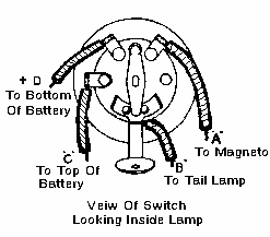
Diagram of Switch Connections inside
Head Lamp of 7-in. Set.
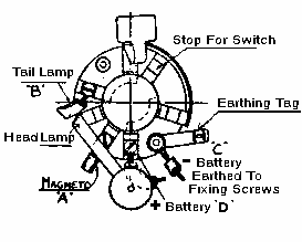
   Diagrams of Switch Connections inside
Head Lamp, 5-in. (or Midget) Set.


   5 1/2-in. SET. This Set differs from the previous two in that the Dry Battery is situated inside the Head Lamp. The 5 1/2-in. equipment employs a small Dry Battery, replacements for which are obtainable at 8d. each from the manufacturers. The Pilot and Tail Bulbs are interchangeable, and are of the screw-cap flash lamp pattern. This 5 1/2-in. Set is employed with the Four-Pole Magneto, and the correct Bulbs are as follows: --
   Head Lamp Main Bulb 6 volt 1 amp. Single contact.
   Tail Lamp & Pilot Bulbs 3.5 volt .3amp. Screw cap.

Diagram of 5 1/2-in. Parking Light Set.


LIGHTING SETS


With the 6-Pole Magneto.
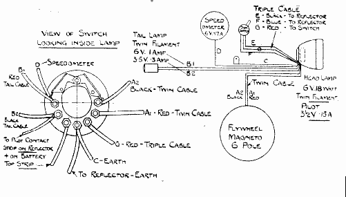
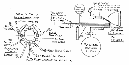
   The 5 1/2-in. and 7-in. Sets just described are used with slight modifications to the switch and employ bulbs as given below to suit the increased output of this magneto.

   5 1/2-in. SET.
   Head Lamp Main Bulb ... 6v. --18/18 watt. (Twin filament).
   Head Lamp Pilot Bulb ... 3.5v. - .15 amp.
   Tail Lamp Main Bulb ... 6v. - 1 amp.
   Tail Lamp Parking Bulb ... 3.5v. -- .3 amp. (Twin filament with above).
   Speedometer Bulb ... 6v. -- .17 amp.


   7-in. SET.
   Head Lamp Main Bulb ... 6v. - 18/18 watt. (Twin filament).
   Head Lamp Pilot Bulb ... 4v. - .125 amp.
   Tail Lamp Main Bulb ... 6v. - 1 amp.
   Tail Lamp Parking Bulb ... 3.5v - .3 amp.
   Speedometer Bulb ... 6v. - .17 amp.

   A Word of Warning. You are strongly recommended to buy your replacement Bulbs for VILLIERS Lighting Sets direct from the makers, or their accredited stockists. These Bulbs are made specially for VILLIERS Lighting Sets and if cheap or imitation replacements are purchased they will probably not be of the correct capacity, and trouble will be experienced either through the Bulbs burning out, or giving insufficient light.


A FEW GENERAL HINTS & TIPS.


  1. (a)    To Start. Fill the fuel tank with petrol and the oil tank with oil. In the case of an engine lubricated by petroil, the two should be mixed together in the proportions of one part oil to 16 of petrol, and this mixture should be made before pouring into the tank.

    (b)    Use Patent Castrol XL Oil, which gives good results on all Villiers engines.

    (c)    Open the handlebar lever of the carburetter about one-quarter way, and set the jet control lever as far as possible towards "rich." Depress the small plunger on the top of the carburetter float chamber until the petrol just commences to overflow. There is no need to allow any petrol to run to waste.

    (d)    Lift the compression release valve, and standing astride the machine, depress the kick-starter pedal once or twice and then give a sharp kick downwards, dropping the release valve lever just before the end of its stroke.

    (e)    When starting up, it is advisable on engines provided with variable ignition, always to retard the magneto to prevent the first explosion tending to drive the engine round backwards. The magneto is retarded by moving the control rod forward towards the cylinder, and is advanced in the opposite direction.

  2. Never flood the carburetter when starting a warm engine.

  3. Ask the manufacturers for a separate leaflet explaining the handling of your Villiers Carburetter, to obtain the best results.
    IMPORTANT - The top control lever of the two-lever Villiers carburetter is an independent control for the jet. This is not to be used as the air lever of an ordinary two-lever carburetter.

  4. It is sometimes advisable to turn off the petrol supply (especially in the case of petroil lubrication), a short distance before stopping at one's destination, so that the supply in the carburetter when re-starting will be quite fresh.

  5. Avoid all sharp bends in the carburetter control wires, otherwise the inner cables will not work freely.

  6. It is wise to filter your petrol through fine wire gauze before filling your tank.

  7. It is important that air leaks should be avoided. The connection between the carburetter and the induction pipe must be absolutely airtight, and after dismantling an engine, new washers should always be fitted at the induction pipe joint, and cylinder base joint, if the original ones have been disturbed.

  8. The common causes of irregular running are as follows: -
       (a)    A dirty sparking plug.
       (b)    An obstruction in the petrol supply pipe.
       (c)    Incorrect timing of the magneto.

    It is impossible for a choked jet to occur in the Villiers carburetter, because the taper needle which constantly works in this jet keeps it clear. Such an occurrence in any other make of carburetter can frequently be a cause of irregular running or failure to start.

  9. Driving shafts should only be taken apart by a skilled mechanic. Special machinery is required for getting these quite true when re-assembling, and as the makers have these facilities, repairs can be undertaken by them at much lower cost than by the average Cycle Agent.

  10. When decarbonising an engine, it is very important that the exhaust pipe and silencer are also cleaned out. It is not sufficient to clean the cylinder and piston head and the exhaust port, but in addition to this the exhaust pipe should be thoroughly cleaned and also the silencer.
    If these parts become choked with carbon, it is detrimental to the running of the engine.

  11. With the Villiers Automatic Lubrication System, make sure your oil tank is air-tight. There must be no vent hole in the filler cap, and the pipe unions must be tight.

  12. The makers really know which is the best type of Sparking Plug to suit each engine, and it is never advisable to experiment with cheap plugs.

  13. Don't use cheap or unknown fuels. No. 1 Quality of any of the well-known Petrols is always safest.

  14. The engine number is stamped on the aluminium crankcase just below the cylinder flange, and should always be quoted, together with the prefixed letter or letters when writing to the makers.

Manufacturers :
THE VILLIERS ENGINEERING Co. Ltd.
WOLVERHAMPTON . . ENGLAND


Back to BIKES page