The Cheshire County Council. Road Mans Van.


General Description

  The van appears to be a late development of the four wheeled contractors living vans, which were usually towed by steam rollers or traction engines. This two wheeled version was probably built in the early nineteen fifties, and was almost certainly intended to be used as a workman's "hut" and towed behind either a roller or a motor lorry. It is made of tongue and groove boarding on a simple frame, with a curved roof covered with roofing felt. It makes an excellent basis for a "caravan" with character, suitable for towing with a Landrover or similar vehicle.

Notes

The drawings on this page are not to scale. Dimensions of timbers follow the industry standards, i.e a piece of timber refered to in round figures as 3" x 2" will in reality be 23/4" x 13/4" when planed. The frames are mortice and tenoned together, and braced by the plywood linning. I have intended these pages to help anyone who is trying to restore a derilict example of these vans, however I can see it would be perfectly possible to build a brand new one. It is the buiders/restorers responsibility to ensure his trailer conforms to the appropriate constuction and use regulations in the country he (or she ) is in. These pages are very incomplete, more drawings and information should be coming soon.

The Timber Chassis

Chassis Cutting list
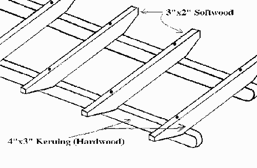
Main chassis longitudinals 2 off.... 121". of Nominal 4" x 3" (33/4" x 23/4") hardwood ( Keruing )
Cross pieces (ends) 2 off.... 78" of Nominal 3" x 2" (23/4" x 13/4") hardwood ( Keruing )
Remaining cross pieces. 5 off.... 78" of Nominal 3" x 2" (23/4" x 13/4") softwood, (middle one, over axle is cut shorter)
Floorboards Nominal 1" T&G to cover area 115" x 78"
Steel angle 21/4" x 21/4" and 1/4" thick plate for tow hitch.

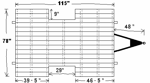
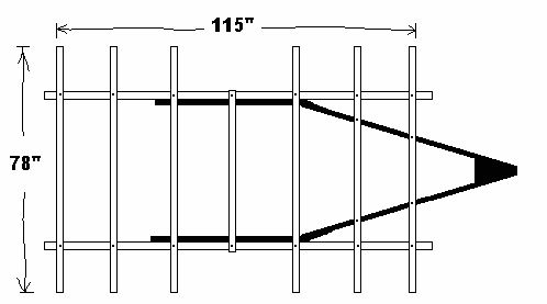
Plan view, including steel tow bar.

The 3"x2" cross members are spaced equally down the chassis. Therefore :-   7 x 13/4" + 6 x 171/8" = 115"   The view shows how the steel angle braces the front section and continues as far as the spring mounts. The longitudinals are fixed 9" in from the sides, making them 60" apart to their OUTSIDE edges. Make sure this dimension suits the the spring mounts on your axle. The axle is positioned about 31/2" behind the centre line. 115" divided by 2, plus 3.5" = 61" from the front.

The whole assembly is bolted together with coach bolts. It may be necessary to counter sink the heads slightly to ensure the floor boards will sit flat. The steel tow bar is like an inverted L it has one flat side bolted to the 4" x 3" with six (three per side) 3/8" bolts, and the other flat side supporting, and bolted to the 3" x 2" crossmembers with four, 3/8" bolts as can be seen on the plan view.


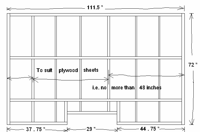
Note that the 29inch wheel arch cut out is not central, and that the tow bar extends 48 inches forward (to the centre of the towing eye, or ball ).

The Axle

  The original axles on these vans were 1.5 inch square bar (solid not hollow) turned at the ends where the hub bearings fit on. They were not really up to the job, as all examples I've seen were badly bent after fifty years service. A much better axle could be made using Landrover stub axles, hubs, brakes, wheels and springs.
Only the central part of the axle and the attachments for the spring shackles would need fabricating. And some ingenuity used to enable cable operation of the brakes. I think some of the 11" rear brakes used the same cylinders as the Rover P4 cars, and as the cars had a cable operated handbrake, a conversion should be simple. For the 10" brakes a pair of Landrover handbrake expanders might be modified to suit.
The End Frames
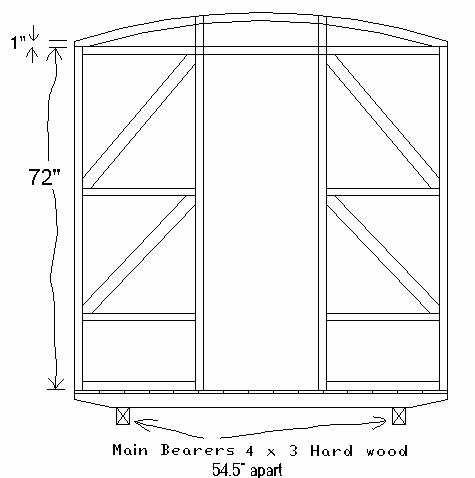
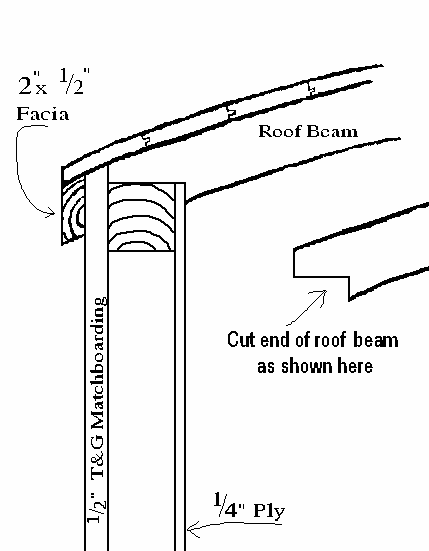
The roof beams have a curve of 6" in 78" . The original ones were 2" x 2" steamed to shape. But those that were rotten on mine were replaced (by laminating with PVA glue) four pieces of 1/2" pine together.
I didn't fix a plywood skin on the rear frame on my van, so I included some diagonal braces.      


The Front Frame
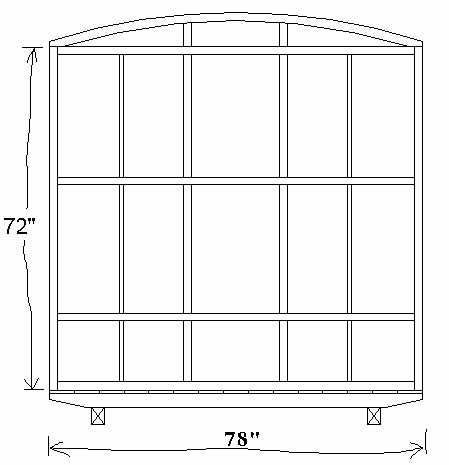
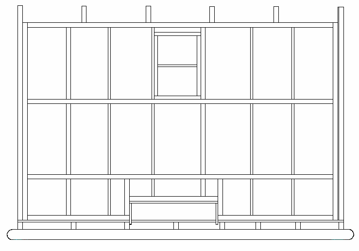
      The spacings, and number of vertical pieces in the frames is not critical. You need a vertical piece where the sheets join and enough other pieces to stop the plywood bending in when you lean on it.

The Side Frames
Side Frame Cutting list
3 off.... 111.5" of 1.75" x 1.5" softwood
4 off.... 72" of 1.75" x 1.5" softwood end posts, and where the plywood joins
4 off.... 72" of 1" x 1.5" stiffeners for walls.
The inner skin of 1/4" plywood in these vans is definitely structural. (There is only the curve of the roof, and the plywood inner skin of the walls to provide the necessary stiffness and rigidity). It MUST be well fixed to the frame, ( Easily done these days by gluing with PVA adhesive, and sufficient panel pins to ensure that the timber/glue is in close contact while curing )
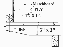
The frames should be assembled, glued, and skinned inside with ply before erecting on the chassis. The side and end frames are then bolted together though their 2"x2" corner posts, and the bottom rails drilled and bolted through the floor boards and through the ends of the chassis cross members.
Do not fix the boards on the outside of the van at this stage. . The interior fittings (seats, cupboards, beds etc.) stiffen the side walls, and you will probably need some extra pieces of wood in walls to fasten it to. So some planning of the interior needs to be done before cladding the outside.

Corner detail and wheelarch cut outs.
    
     The picture on the left says the facia is 1/2" thick, that is a misprint, it sould be at least 3/4" thick and about three inches longer at each end than the van sides, to allow the roof to over hang.


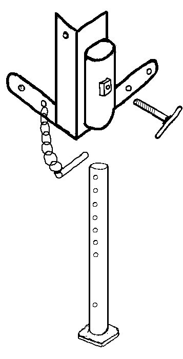
Steel work on the corners is about 8" high, 2 off each hand as the prop clamps protrude at the front and rear, not sticking out at the sides of the van. Adjustable props are about 42" long.


Back