DESCRIPTION OF CARBURETTER.
FUEL FEED. The float chamber (s) and the mixing
chamber (h) are in two separate pieces, and bolted
together by flange (n1) and studs (r) between the
flanges are a petrol filter gauze (m) fitting into recess
(m1) and a paper washer (n), making a petrol tight
joint between them. The carburetter contains only
one jet (k] which is well submerged in the fuel ; it is
screwed into the end of the needle jet (j), and is easily
accessible by undoing the cap (l), under the mixture
chamber. The fuel from the float chamber flows
through the main jet (k) and finds its level in the
needle jet (j), which just protrudes into the mixing
chamber under the throttle. The petrol pipe connec-
tion under the float chamber is horizontal banjo (u) to
take a rubber pipe ; it can be swivelled round in any
direction and locked by nut (w).
The petrol level is maintained by a float (p] and needle
valve (v), the needle is not adjustable. The needle is
attached to the float by a wire bow on the top of the
float which engages in a groove in the needle.
The fuel passage from the float chamber to the jet
chamber is very large and protected by the gauze
ring (m) fitting into the recess (ml).
MIXTURE CONTROL. The throttle (g) is of the.
piston type sliding up and down ; it has two slots
down its length, the deeper one for engaging the control
cable and the shallower one to slide over a screw to
locate its position. The throttle has a cutaway on the
air intake side at its end nearer the jet —which cutaway
can have different angles to operate for the purposes
of mixture control at lower speeds.
The throttle carries a taper needie (f) which protrudes,
into the needle jet (j) : there are several positions for
this needle in the throttle so that the mixture may be
adjusted correctly by its relation to the throttle
opening. The needle travels up and down as the
throttle is moved because the needle clip (e) rests on
the throttle and is held there by the throttle spring (d).
The throttle needle is accurately ground to a suitable
taper and slides in the needle jet which has an accurate
bore, the differences in diameters providing a means
of controlling the flow from the main jet to correct
the mixture at mid-throttle openings.
In conclusion; a correct mixture is maintained at all
throttle openings, viz. ;—
At full throttle, by the size of the main jet.
At small openings, by the throttle cutaway and, in
intermediate positions, by the position of the needle.
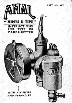
For starting from cold the air filler is provided with
strangler shutter.
_______________________________________________
NOTE-The jet (k) and the needle jet (j) etc. are too small to be
interchangeable with those in the larger AmaL range of carburetters.
| |
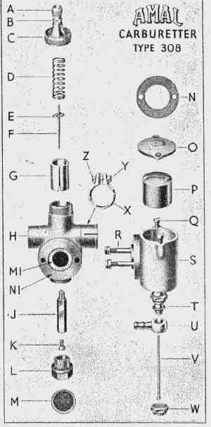
INDEX TO EXPLODED VIEW OF CARBURETTER 308.
(a) Cable adjuster. (p) Float (bottom feed).
(b) Adjuster lock nut. (q) Coverscrews for fl. cham.
(c) Mixing chamber cover. (r) Holding studs and nuts
(d) Throttle spring. for float chamber.
(e) Throttle needle clip. (s) Float chamber, bottom
(f) Throttle needle. feed.
(g) Throttle valve. (t) Needle valve seat and
(h) Mixing chamber body. petrol connection.
(j) Needle jet. (u) Petrol pipe banjo.
(k) Main jet. (v) Float needle.
(l) Jet cover. (w) Petrol pipe banjo nut.
(m) Filter. (x) Outlet clip.
(n) Fl. cham, flange washer. (y) Outlet clip screw.
(o) Cover for float chamber. (z) Outlet clip nut.
The small screw in the side of the throttle chamber is not seen :
this screw acts as a guide for the throttle.
HINTS & TIPS ON CARBURETTER TUNING.
Provided the petrol-oil mixture is to the engine-makers'
specification and is well mixed and that there is an
ample flow to the carburetter, any incorrect carburation
must be due either to too weak or too rich a mixture.
If the mixture is suspected to be rich make sure that
the float chamber is not flooding : if flooding, clean out
all impurities in the petrol pipe and float chamber.
Before " tuning " the carburetter, decide at what
throttle opening any fault appears. A weak mixture
is evident by spitting in the carburetter or by inability
to open throttle. A rich mixture is evident by lumpy
running, smoky exhaust, and oily sparking plugs.
If the error appears at :-
Full throttle, alter the main jet (k).
At small throttle openings, select a throttle (g) with
different cutaway. A larger cutaway weakens the
mixture and the smaller one richens it.
At half throttle, adjust the needle position. Lowering
the needle (f) weakens the mixture ; raising it
richens the mixture.
When the above has been attended to. any correction
to the slow running must be done by the cutaway of
the throttle.
FUEL DRIPPING FROM PETROL PIPE
CONNECTION UNDER FLOAT CHAMBER.
The hexagon nut (w) under the float chamber should
be tightened gently and firmly only to secure, in a petrol
tight manner, the banjo petrol pipe connection (u)
between its washers : it must never be overtightened
with a large spanner, otherwise this will result in
breakage. If petrol appears to drip from here it may
be seeping from the end of the rubber pipe which is
pushed over the serrated end of the banjo connection (u).
Alternatively, the drip may be due to flooding over the
float chamber cover (o) due either to excessive vibration
or to impurities (grit, fluff, etc.) lodging on the needle
valve seating and so preventing the needle valve (v)
from closing tight. There is an air vent hole in the rim
of the cover (o) which must be clear.
Genuine flooding can only be due to a bent float needle,
an excessively worn groove in its conical head, float-
bow jumped out of needle groove or a punctured float.
25M/2/51. W. Printed in England. |
 CARBURETTER CONTROL.
The carburetter controls the volume and quality of
the mixture by a sliding piston throttle which is
operated by a flexible wire and cable actuated by a
lever on the handlebar.
To start from cold, close the air shutter strangler in
the air filter, open and close the throttle a few times
and then set it about 1/4 open ; proceed to start the
engine, and when it is going, open the air shutter, and
throttle down.
CARBURETTER  CONTROL.
The carburetter  controls  the volume  and  quality  of
the mixture by  a  sliding  piston  throttle  which  is
operated by a flexible wire and  cable  actuated  by  a
lever on the handlebar.
To start from cold, close the air shutter  strangler in
the air filter, open and close the throttle a few times
and then set it about 1/4 open ; proceed  to  start the
engine, and when it is going, open the air shutter, and
throttle down.